|
|
|
Posted by Bill Stanley on October 17, 2003 at 09:02:43: Text DWG translations follow the following rules. The latest updater is needed for the rules to be followed Outgoing fonts. Outgoing fonts are mapped as follows. Bold is supported for the above fonts. The other side will usually have the fonts listed. Empirically derived height compensations are used to adjust for the difference in font metrics for the above fonts. The other fonts in your drawing are mapped to your default font choice in write options. Incoming fonts are mapped as follows. The other incoming fonts and shape fonts are mapped to your default choice in read options. 'Trebuchet MS' and 'Arial' are reasonable substitutes for the shape fonts. Incoming fonts seem to have a shorter line length than most Mackintosh fonts and can easily over run the intended space depending upon your default choice of incoming font. The butt-ugly font group is rumored to be working on txt and RomanS shape fonts and maybe other fonts for Macintosh. (beta txt beta RomanS) Avoid scaling after translation. The natural tendency is to scale after translating. Don't. Scaling plays hell with the text. Translating again with a different scale is a far superior technique. Translating again takes a few more minutes but will save hours of agony and grumbling. So what if you need to translate ten times because you didn't get the scale from the consultant. What works for me is to translate at increasingly larger page sizes until the text and arrowheads appear to be the correct size. Calling the consultant and communicating is a much better approach not available to me. Don't hesitate to use large page sizes even up to 200 by 200 inches. The natural tendency is to believe the consultant wouldn't draw off the printed page. Not a good assumption. You have no idea if the consultant doodled off the printed page and he probably doesn't remember either. Also software misunderstanding often leads to far away objects that can no longer be found. Model space and extents must by nature include everything including those forgotten entities pitched off page by mistake. A mistaken divide by zero often results in objects in infinity. Your translation success and failures are the basis for future improvements but only if they are known. Improvements are almost always a result of someone presenting a problem with sufficient evidence to reproduce the problem and test code changes for improved results. Currently merge operations on paper/model space are being tested with only few dozen drawings with both spaces are available for testing. Thanks for listening and we hope the above information will be helpful.
Bill Stanley |
|
Peter Hsu writes: Dear Professor: One of the MOST important and fundamental issue in our work is dealing with SCALES. I have wasted many man-hours trying to figure out what scale the opened ACAD file was drawn in, and how to convert an ACAD file of a civil drawing, drawn in 1:20 or 1:50 scale to 1/8"= 1'-0" First of all, there is no simple magic formula for handling every conceivable situation. Believe me, if there were, Engineered Software would have already built it into the translator. The best we can do here is a short overview of some of the variables and parameters that you can adjust, and hopefully you will see which adjustments have which effects on the file that you bring into PowerCADD. If you get a file that resists your first effort, change one setting and try bringing it in again; loooook at the results and think about what happened. When you import a .dwg or .dxf, what is actually happening is that PowerCADD is reading the heiroglyphics in an AutoC*D file, and converting them to objects that are useful and comprehensible to PowerCADD (and to you and me). The better the clues that you give PowerCADD about what you expect it to do, the closer your results will match your expectations. Amen. There are two parts to your conundrum: I am always dumbfounded by the seemingly random default scale factor that the dialog box brings up when you go to import an AutoC*D file. We'll look at that in a little while. Also, it is important to remember that AutoC*D does not use scales. So, in the translation we will be adding scale information to unscaled raw data. But one thing at a time. |
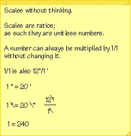
Scales The fundamental component of a scaled drawing is the absolute scale. This is the physical relationship between the object being depicted and the drawing object. It makes sense to draw continents at a very small scale ( perhaps 1" = 100 miles ) and to draw computer chips at a very large scale ( maybe 1" = 1/10,000 of an inch ).
The absolute scale of the continental map at 1" = 100 miles is 1:6,336,000 (i.e. there are 100 x 5280 x 12 = 6,336,000 inches in a hundred miles)
The absolute scale of the hypothetical chip drawing is 10,000:1
The ':' is the ratio of reality to depiction. you can think of it as a 'divided by' sign as well. It indicates the relationship between the object and the drawing.
Metric Scales
are the easiest. they are already absolute scale, there is no "scale factor".
In a 1:100 drawing, any distance represents 100 x (itself).
So 1 centimeter represents 100 centimeters (1 meter). If you measure using your big toe, 1 big toe in the drawing represents 100 big toes in reality (the distance, whatever it is).
So in metric scales there is a single direct proportion between the scaled measurement and what it represents. It is just multiplied.
So now you know how to handle it when you are forced to deal with the fictitious metric dimensions (why the rest of the world refuses to use real dimensions is beyond me -- I mean why would you base your whole system of measurement on 39 3/8 inches, for crying out loud? -- that is rational?!?)
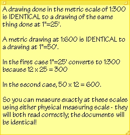
1:300 == one inch to twenty-five feet.
Engineering ScalesThese are one step removed from metric, because there is a "foot factor" involved.
An engineering scale of 1":30' for example is actually equal to 1:360 scale (since there is a hidden 12 inches to the foot involved) -- To get the same units on each side of the ':'(the colon) you have to multiply both sides by 12. Taking 1"=30' and multiplying by 12 you get 12" = 360' OR 1 foot = 360 feet.
Architectural Scales
are typically two steps removed, because they are written 'upside down' and say, for example 1/8" = 1'-0".
1/8" = 1'-0" is actually equal to 1:96 scale, because there are 96 eighths of an inch in a foot (12 x 8).
You still use the same trick to get the same units on each side of the colon.
Try it for 1/4" = 1'-0"; that is like saying 1" = 4'-0" (4 x each side), which is the same as saying 12" = 48'-0" -OR- 1'=48' or 1:48
To convert between scales, simply establish the absolute scales, then do a straight proportion.
(See the convenient Bullpen Scale Ratio Table here) So if you have a drawing at 1/4" and you want it at 1"=30', your source information is at 1:48 and you want it at 1:360. So scale it by 48/360 (or .13333%). This works correctly every time, once you establish the source and target absolute scales.
Absolute scales are INDEPENDENT of units - it doesn't matter if you are using cubits or meters or potatoes, if you know the absolute scale of a drawing, you can figure out how big the object is in reality (feet and inches).
Since PowerCADD dialog boxes accept "calculator style" input, in order to accurately resize an object to a different scale, you can just select the objects you want to transfer, select scale, and key in "48/360" in the scale factor box. It is actually much more accurate to do it this way, since the division results in a continuing fraction which is stored in double precision inside the computer (if you enter 0.13333% you will lose the benefit of beaucoups de decimal places, although it probably doesn't matter much in the real world).
Even easier is to simply Cut and then Paste Special at Scale, and give your brain a rest (highly recommended).
Now, let's try the doing the AutoC*D thing.
First of all, AutoC*D is designed to be difficult, so it takes some patience. Often you will have to try importing a file five or six times before you can find the combination of settings that works. What you are looking for is the right combination of settings that will give you the most useful form of the document. Patience and mental effort will pay long-term dividends.
Typically what happens is you will receive a 1.3meg .zip file which expands into a folder that contains 19 items, including .fmp files, .ttf files, a few .shx files and maybe a .txt file and a .ctb. Oh yeah, did I mention there might even be a couple .dwg files as well? You probably want the largest one of them, but you might want them all.
You will need to establish the following:
WHAT SCALE DO YOU WANT IT IN?
and
WHAT UNITS DID THEY USE TO DO IT?
As we will see, it can also be very helpful to know what size sheet the file was originally intended for.
It may require some crafty detective work, bribery, or blackmail to find out from the person who prepared the file what Units they have used, it is worth the effort.
By the way, UNITS are a thing in AutoC*D, they are something AutoC*D people know about. Just try to find out what the units are. You can casually say, "Oh, by the way, what Units do you use?" It is funny, they will just tell you, "Oh, we use---" and they will say something, and that tells you what their Units are.
If you cannot acquire this information, skip to Plan B (below).
For the purpose of argument, let's stipulate the following conditions:
We are trying to open a file called..oh, just for fun, let's call it XRO-KFG.dwg. (Of course, in the real world, nobody would really name a file XRO-KFG.dwg, but we will allow ourselves artistic license because we are in the Bullpen.)
And we know that we want to see it at a scale of 1" = 20' (one inch equals twenty feet) and the units they used were FEET.
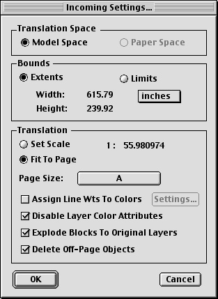
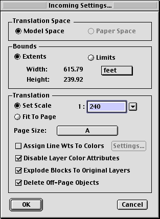
Plan A Drag and Drop the XRO-KFG.dwg onto PowerCADD. We get a dialog box that looks like this:
WHOA. what the heck is going on here?? I know AutoC*D users like to do things the hard way, but what is up with this 1:55.980974 scale?
Before we get going, let's try something:
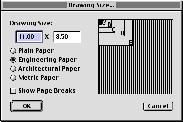
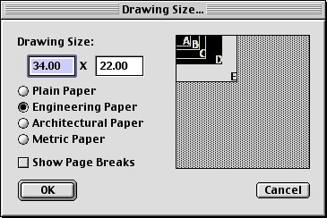
change the page size from A to B..
(click the A button)
Hmm. that's interesting.
We changed the page size and the bizarre scale chagned from 55.9... to 36.2...An A size sheet of paper is 11 inches wide and a B size is 17 inches wide. I wonder if 55.9 / 36.2 is the same as 17 / 11?
Son of a gun! it is. That means that the scale that this dialog defaults to is nothing more than the ratio between the data and the SHEET SIZE you have selected. It has nothing to do with the scale of the drawing.
It has nothing to do with the scale of the drawing.
It has nothing to do with the scale of the drawing.
The value of the scale ratio is PowerCADD's best guess at aligning the AutoC*D data with your chosen page size...once you have correctly established your desired page size you can consider this a good starting point.
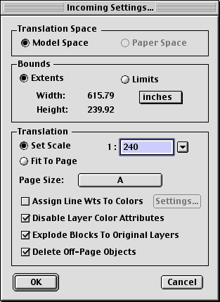
So far so good. Now, let's try to bring in the .dwg file, we'll change the scale to the scale we want, 1":20'.
(one inch = twenty feet)The absolute scale of 1"=20' is 1:240, so that is what we enter in the dialog box.
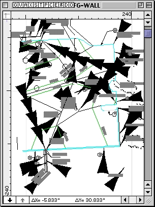
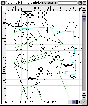
Now cross your fingers...Let's look at the file.
Blast and damn.
Garbage.
It looks like it didn't work.>:-(
The reason it didn't work is that we forgot to set the UNITS.
Go back and look. The daggone units are still set to inches.
That is why we got such BOGUS arrow heads. And nothing worth using.
But, as John Carter used to say, while there is life there is hope. (or was it Carson Napier?) Let's try the whole thing again. Close that window without saving.
Drag and Drop the file on PowerCADD again, and this time set the Units to Feet (instead of inches) and set the scale to 1:240 again..
remember,1:240 is1"=20'
use the ABSOLUTE SCALE.
And it looks like we now have our own PowerCADD copy of XRO-KFG.dwg -- now we can give it a real name.
Just to be sure, we can go into the document and find something of known size and measure it, and sure enough, every thing is good to go.
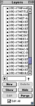
Now all we have to do is sort through all the wonderfully informative AutoC*D layers, and we are home free.
Let's see did that belong on KRO-XTMEXCONTUTIL2 or KRO-XFMEXCONUTIL2? hmmmm.
I am SO glad I get to use PowerCADD. think we're done? look at your scroll bar --->
Interlude
As this page has evolved, I got some extremely helpful comments from quite a few folks, and especially from Evoy & Associates, PowerCADD Distributors in Canada, who helped correct most of my erroneous misconceptions; for example, I thought that it mattered what scale the original drawing was prepared at (in AutoC*D).
It turns out this does not matter in the least.
However, it is helpful to know the sheet size they used, because by setting your sheet size to match theirs, you will probably get a very strong clue as to what scale makes the most sense to use to bring their information into PowerCADD (in most situations you probably want it at the same scale it was created).
If you set your sheet size close to theirs, the scale factor that appears in the dialog box can serve as a helpful guide for you to establish the scale that will provide you with useful drawing information:
(Assuming your AutoC*D ally hasn't defeated your strategy by drawing out of bounds...) Since AutoC*D uses non-relational Units, which are then assigned a value (centimeter, inch, foot, meter) by the user, all AutoC*D drawings are actually at 1:1 scale (we'll agree to call it actual size, although this is only a useful fiction). It will be fruitful to study the following information carefully:
So what do we make of this:
In your example you used 1:36.222983 to be presented by the dwg dialogue.
Then you suggest using a 1:240 scale setting.
This is an incorrect directive.
Always just "round up" the caculated scale factor to the next most logical scale (i.e. 1:40 if metric or 1:48 if imperial).
Well, wait a minute, let's take a look at this...
Here we go again:
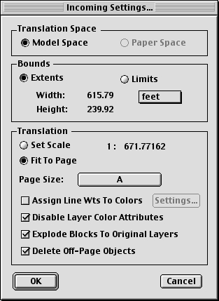
Drag and Drop the XRO-KFG.dwg on PowerCADD. Set the Units to Feet (instead of inches)
Look at the scale factor again, 1:671 is PowerCADD's way of telling us that in order to fit this drawing on an A size sheet of paper it will have to be somewhere between 1"=50' and 1"=60'...
But we want it at 1"=20', so let's take a look at the sheet size dialog... Click the A button.
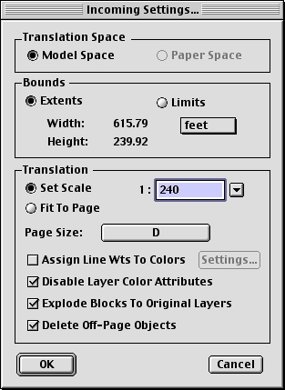
We make a call to the office and find out that they did the drawing on D-size paper, so click on the D-size page setup.
And we see this..
click OK...
PowerCADD has helpfully determined that in order to fit this drawing on a D-size sheet, the scale must be about 1:217.
Since we are shooting for 1:240, we know we are now on the right track.
One more thing to do and we will be there..
Set the correct scale factor (1:240) and we can become productive again. What is the big deal with setting the sheet size? Why should that matter, why shouldn't I just set the sheet size I want and the scale I want and go from there? you ask.
One word: Fonts and Text.
Remember AutoC*D doesn't really understand scale, it only has Units. That is why they had to invent paper space, to help their victims get somewhat predictable output. So Text in AutoC*D is managed differently than in PowerCADD; if you use a page size that is relatively close to the original, there is a much greater liklihood that you will get a drawing that you can use with less tweaking.
(This is a very interesting and deep topic...perhaps for another day, another page, maybe even another website...)
Of course, none of the foregoing will compensate for a source .dwg that has been prepared mindlessly or is full of miscellaneous junk, nothing can correct for that. ..well, maybe a #2 Hem-fir 2x4 about 6' long would help make a good start (it works on me).
Plan BIn Plan B you are given a document from an alien galaxy, perhaps a parallel universe, in which it is impossible to communicate with the originator of the file, perhaps their planet was burnt to a cinder centuries ago, perhaps there is no intellegent life there, but in any case you have NO EARTHLY IDEA what the heck kind of data you have. Perhaps they don't know what their Units are either. What to do?
Try plan A and guess. (HA!)
Open the file and see if there is a clue about the scale in the title block or on a drawing title, they might have slipped up and left a notation somewhere.
If it is a civil drawing the units are probably feet. If it is from a country where they use metric dimensions, guess about meters or centimeters. If you get huge arrow heads, guess again, and pick larger units (vice versa is a safe bet as well). Each time you open the file, try to find something of known size and measure it. If it is on the money, great Save it and Move On. If not, close without saving and try again. It won't be long before you find the right combination. If you are systematic about it, it 'll be over pretty quickly.
Review: Suggestions
- Determine the Units and the original Sheet size of the document to be imported as best you can
- Set the Units to match and the sheet size as close as possible in the import dialog box.
- Bump up the Scale to the closest next-highest integer absolute scale that makes sense.
- If unsuccessful, try again, if you change only one variable at a time as you do it you will better understand the process that your machine is using...
There is also an excellent page at Engineered Software's site about importing:
http://www.engsw.com/Help/Hereshow/Incoming DWG.html.Some additional user translation tips are at the Bullpen Translation page.
By the way, Gary Veasy points out:I always deselect "Delete offpage objects". It seems that I have experienced situations where I have translated the entire sheet sucessfully but it is slightly off the page. In this case I can simply Select All then reposition making sure that all layers are on. If you do not deselect this option, off-page objects will be lost forever. (and you wouldn't even be aware that you had lost data.)
Additionally, I have many times encountered rotated dimension text. In this case, use the magic wand or PC selection filter to select only the dimensions. Then choose command-E and check or deselect "rotate text". Sometimes it has to be done twice for some reason but it does initially or eventually rotate the incorrect dimensions back to their proper orientation.
Thanks, Gary.
If you have read this far, award yourself a brass figlegee with bronze oak leaf palm, First Class. The errors on this page are mine (all rights reserved), and I will be grateful for any feedback, input, further contributions, or corrections: just send a note to mda@rwmaia.com
| Got
another issue? Or a comment on this one? The
professor is always interested. The professor is also grateful for all the help he got with this page, especially from Evoy & Associates. |